JGK
Gabe Kozielec

USC AME 481 capstone

Aircraft D conceptual design

Spring 2026

Sizing and mission trades for a conceptual 201-passenger airliner.

Representative photograph, not this project: an Airbus A320neo banking in flight.

Stand-in, not this project · Shougissime · CC BY-SA 4.0 · cropped

Used here

Tools

  • JetSizer-II
  • Aircraft sizing
  • Mission analysis
  • Trade studies

What I did

  • Developed a conceptual 201-passenger, 2,006-nmi, Mach 0.75 airliner, integrating cabin layout, wing and tail sizing, landing gear, propulsion, and mission performance.
  • Evaluated fan diameter, cruise conditions, materials, range, and wingspan against fuel-burn and operating-cost estimates.
  • Documented design limitations, including an unresolved pitch-rotation requirement, and proposed landing-gear and tailcone refinements. The study is a conceptual design, with model-based performance estimates.

Figures

From my final report. Performance values are model-based estimates for a conceptual design.
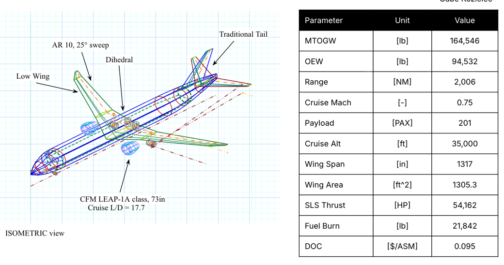
Isometric view of the Aircraft D narrow-body airliner beside a table of its main design parameters.
Figure 1a. Isometric view and design summary: 201 passengers, 2,006 nmi, Mach 0.75.
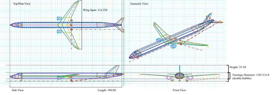
Top, side and front views of Aircraft D with overall dimensions.
Figure 1b. Three-view with walkaround dimensions.
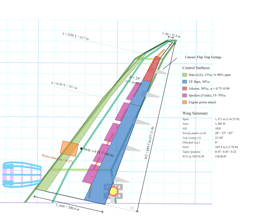
Wing planform showing slats, flaps, ailerons and spoilers.
Figure 12. Wing control surfaces and high-lift devices.
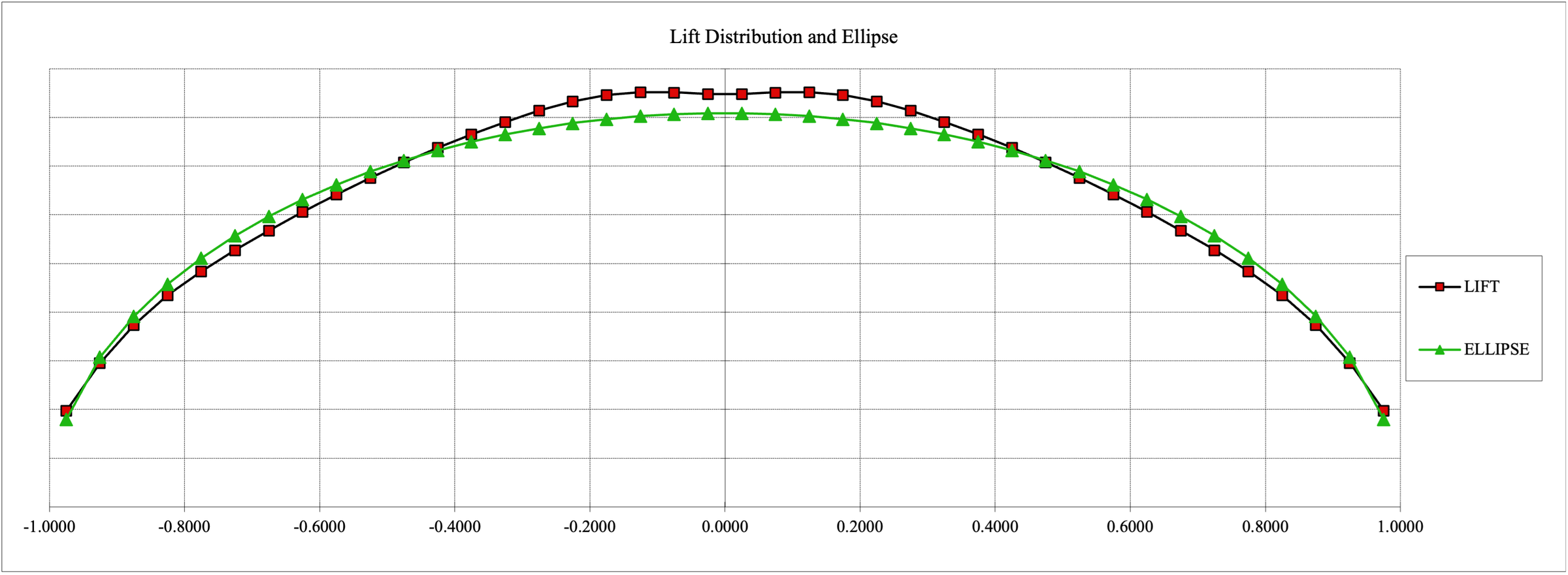
Chart of wing spanload plotted against the elliptical distribution.
Figure 9. Wing spanload against the elliptical optimum.
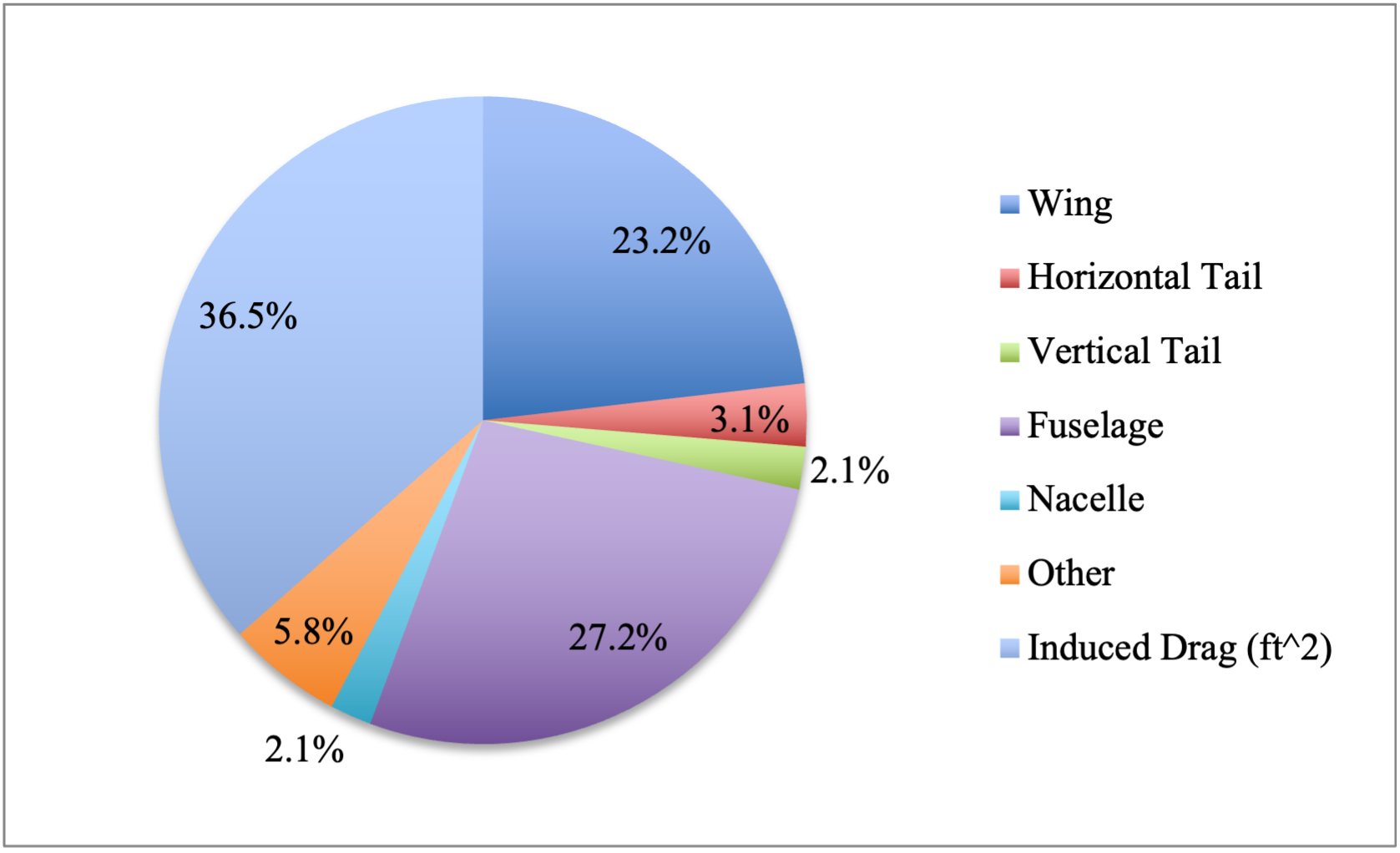
Pie chart of cruise drag by component, with induced drag the largest share.
Figure 20. Cruise drag breakdown at the converged design point; induced drag is 36.5%.
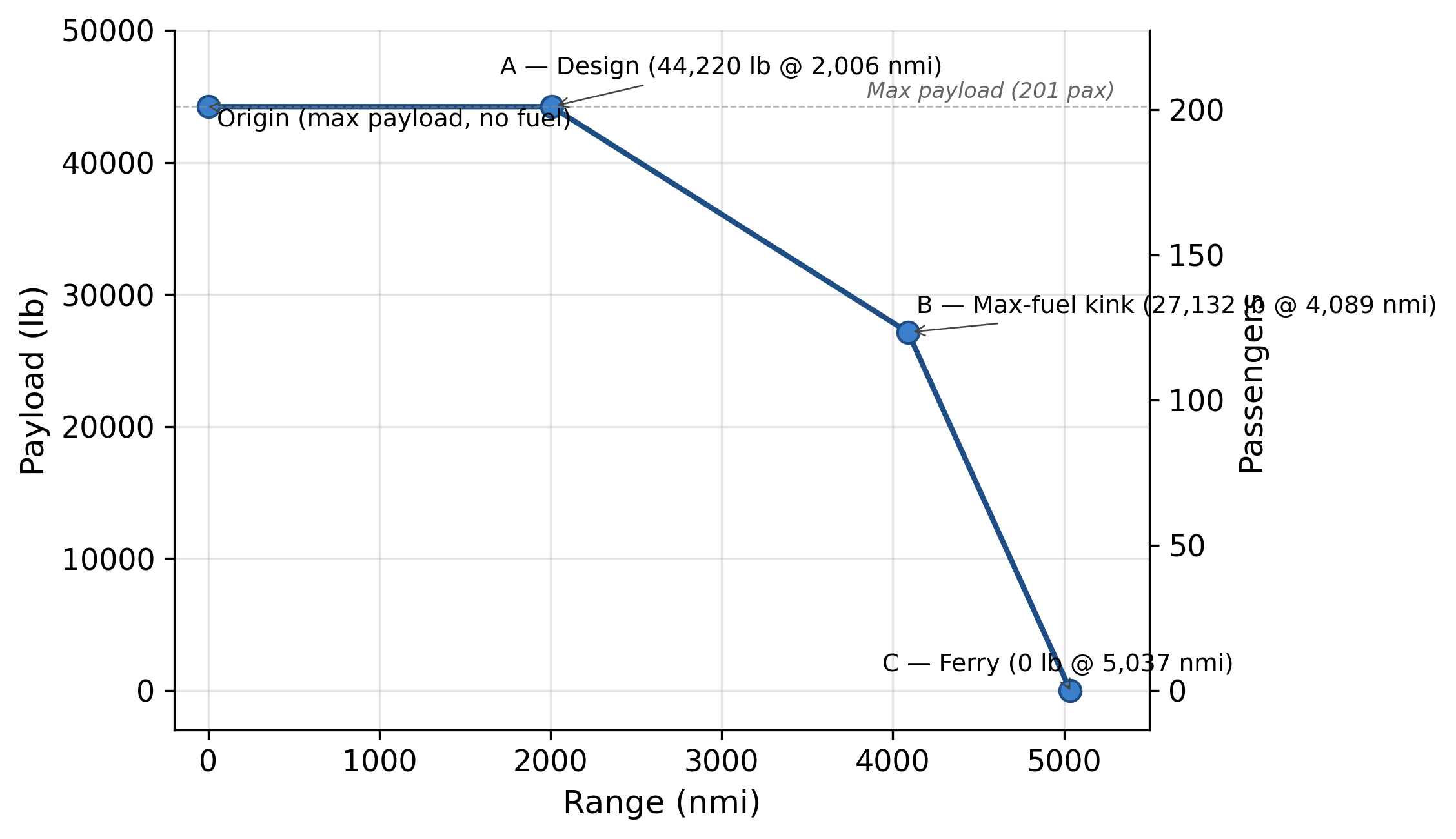
Payload-range chart marking the design point, maximum-fuel point and ferry range.
Figure 22. Payload-range envelope, with the design point at 44,220 lb and 2,006 nmi.
Isometric view of the Aircraft D narrow-body airliner beside a table of its main design parameters.Figure 1a. Isometric view and design summary: 201 passengers, 2,006 nmi, Mach 0.75.Top, side and front views of Aircraft D with overall dimensions.Figure 1b. Three-view with walkaround dimensions.Wing planform showing slats, flaps, ailerons and spoilers.Figure 12. Wing control surfaces and high-lift devices.Chart of wing spanload plotted against the elliptical distribution.Figure 9. Wing spanload against the elliptical optimum.Pie chart of cruise drag by component, with induced drag the largest share.Figure 20. Cruise drag breakdown at the converged design point; induced drag is 36.5%.Payload-range chart marking the design point, maximum-fuel point and ferry range.Figure 22. Payload-range envelope, with the design point at 44,220 lb and 2,006 nmi.

Report

Final design report · 54 pages · PDF, 8.3 MB